

Catlink
Distribution Hub Installation information

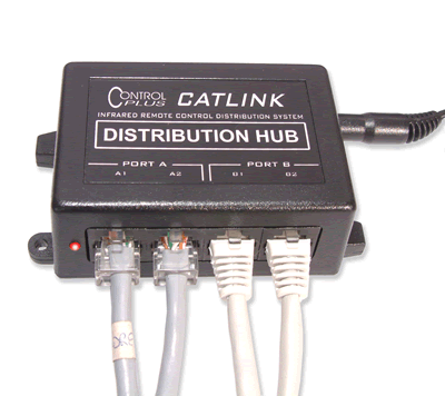
The Distribution hub is connected to the IR distribution network via four RJ45 sockets which are wired with pair 4 providing power and signal reception for IR receivers and pair 1 driving emitters. This leaves pairs 2 & 3 for other applications such as telephone or 10baseT network if required.
The four RJ45 connectors are grouped
into two pairs (designated 'ports A & B') providing two independent IR
receiver circuits. Each of the two IR reception circuits can support up to
6 receiver heads, therefore providing support for up to 12 receiver heads
per hub.
All RJ45 connectors can drive the Emitter network and can be parallel wired
to Emitter signals of extra hubs thereby allowing larger networks to be built
up from multiple hubs.
Each RJ45 connector has 8 pins
(4 pairs) and the hub uses 2 pairs of pins for connection.
All four connectors are wired in the same manner.
Pair 4 (RJ45 pins 7&8) connect to the receiver heads and hub provides regulated power to this pair also to power connected receiver heads. This allows the feature of only requiring two wires (i.e 1 pair) to connect receiver heads to the hub.
 |
The hub supports two independent receiver circuits wired to each of the two ports. This means that if the Port A circuit becomes inoperative due to overloading, sunlight flooding or short circuit, then the Port B circuit will continue to operate and vice versa. On all sockets, Pair 1 (pins 4 & 5) connect to Emitters circuit that drives the emitters positioned over the infrared reception windows of the equipment to be controlled. Signals received on any RJ45 receive circuit will produce emitter drive signals on pair 1 (pins 4&5) of all RJ45 sockets. |
The indicator LED adjacent to the
connectors flashes whenever a signal is being driven out of the emitter circuit.
The hub is powered by 13.8~18V DC via the DC socket. Current rating is dependent on size of system but minimum recommended rating is 13.8V DC @ 0.5A. Max current rating for hub is 1 Amp.
Note: Most 12V DC @ 1Amp unregulated power adapters will be suitable for powering the hub as these typically have an unloaded voltage of around 15V.
EXAMPLE CONNECTION ARRANGEMENTS
1. Simplest Arrangement - No Patch Panel
In the simplest arrangement
where no patch panel is to be installed the hub can be simply connected to
a series of parallel wired RJ45 wall plates and the hub attached at some place
in the arrangement with a signal patch lead.

Connection of the of the emitters
and receiver heads is done by just plugging them into the desired wall plates
- no other cabling required.
This is the simplest arrangement to install but does have the disadvantage
of not being a structured cabling system.
Note: do not string more than six wall outlets at a time.
2. Typical RJ45
Patch Panel Arrangement.
Most structured cabling systems employ at least one patch panel which all
RJ45 outlets terminate to. This is referred to as 'star-wiring' and allows
definition of outlet function by use of patch leads.
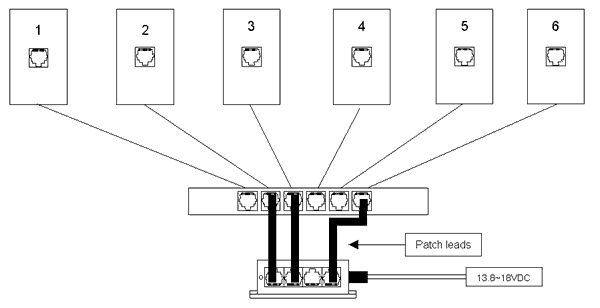
In the example below the Distribution Hub is connected to wall plates 2, 3
& 6.
Connection of the of the emitters and receiver heads is done by just plugging
them into the desired wall plates.

The number of outlets supported
can be extended beyond the four provided by the distribution hub by providing
option in the patch panel for parallel connection of outlets to a single Hub
socket. Do not attach more than 6 outlets to a distribution hub port.
3. Other types:
110 Patch Panels.
Other types of installations using 110 patch panel (i.e pair level instead
of cable level management) may also be employed and in this situation special
patch leads linking the hub to the 110 patch panel are required.
More about Patch Leads ..
In situations where
a given outlet is to be used for more than one thing at a time (for example,
used as a receiver head on pair 4 and as a telephone on pair 1 or 2 and a
dual socket is installed to handle this dual function), the patch lead that
connects the Distribution Hub port to that particular outlet in the patch
panel can be made so that only pair 4 is connected thereby eliminating the
chance of cross connection with the telephone circuit.
After installation, if you encounter problems see the trouble shooting guide for further guidance.